Gears Engineering and Design Equations for American Standard Fine Pitch Worms and Wormgears Per. Worm Gear Module mm 62 Pressure angle deg 20 Lead angle deg 17896 Center distance mm 125 Number of teeth 3 31 Pitch circle diameter mm 576 1924 Averaged diameter.

Pdf Worm Gears Rohan Vats Academia Edu
The worm wheel is analogous to a nut that fits on the.
. Selection of Materials Choose the suitable material for worm and worm gear from PSG Data book page no. A worm wheel or worm gear is a cylindrical gear with flanks cut in such a way as to ensure contact with the flanks of the worm gear. Accounting information systems seventh edition.
In this series we explain how to design gears and peripheral parts according to procedures using simple mechanisms. Mm so try m 2. It may be noted that the helix angle on the worm is generally quite large and that on the worm gear is very small.
The worm has 2 teeth and the worm wheel has 41 teeth. Calculations for gear 2. A worm wheel or worm gear is a cylindrical gear with flanks cut in such a way as to ensure contact with the flanks of the worm gear.
From the axial force transmitted to the worm and the total stiffnessof the worm ROG calculated above we obtain6 RDG - 01J From the mean equivalent stiffness. View Worm Gear Design Procedurepdf from ME ME481 at University of San Jose - Recoletos Basak Cebu Campus. An electric motor or engine applies rotational power.
Load calculation of gears 239 115 Calculation of load on worm gear A worm gear is a kind of spigot. A worm gear drive is used to transmit 22 kW between two shafts which are 225 mm apart. The axialtransverse module is 4.
We determine the distribu-. Line of contact is at angle. They are uniquely suited for static-load applications because of their tendency to self lock under.
A self-locking worm gear can be designed by making the lead angle le thanthefrictioll anglewhich is defined as the arc tangent of the coefficient of friction The static coeffi- cient of frictioni20. 24 full pdfs related to this. Worm lead angle ie.
Worm gears were originally designed as jacks for raising and lowering weights. A high-efficiency worm-gear speed reducer is desired to accept 20 hp from a 1750-rpm. Contact ratio is higher quieter.
Full pdf package download full pdf package. M 2 gives a face width less than the catalog value of 25 mm so OK. A search procedure for a rational design of a worm gear of a drive mechanism for a tool magazine using the main criteria for the effective functioning of a metal.
Choose proper lead angle λ and normal pressure angle φn as per T-XVI-16. αW λ 90. Geometrical analysis of hobs used in the production of ring gears with cylindrical or conical worms.
High gear ratios of 2001 can be achieved. 4A broad type of mathematical modelling is required. Y38 037727 n 5594 rpm.
13-17Force AnalysisWorm Gearing Types of Gears Spur gears have teeth parallel to the axis of rotation and are used to transmit motion from one shaft to another parallel shaft. Initial contact is at point instead of line gears are quieter. Note that meshing gear must.
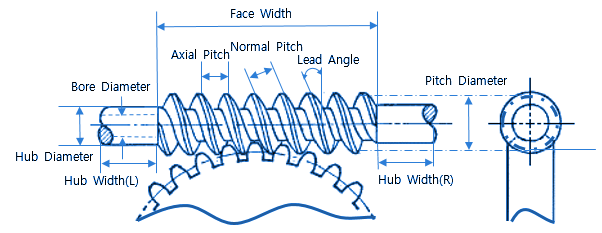
Look at the picture. A worm gear consists of two primary partsa shaft with a spiral thread the worm and a toothed wheel worm wheel. Thus it is usual to specify the lead angle.
845 Most cases steel is selected for worm and bronze is selected for worm wheel. Causes sideways axialthrust loads. M 2 gives valu e for face.
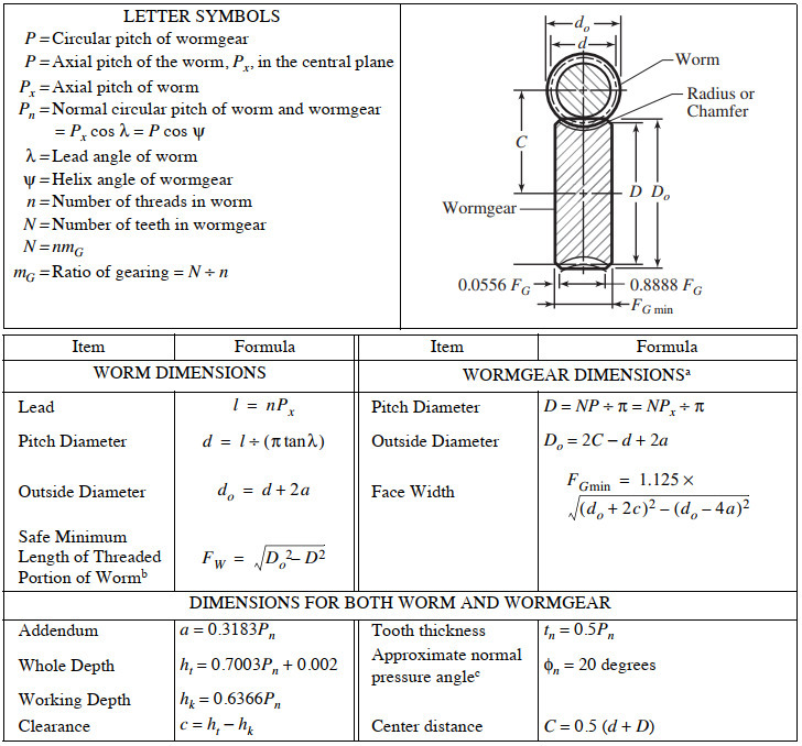
Of Worm Gear Worm gears are used for transmitting power between two non-parallel non-intersecting shafts. The worm wheel is analogous to a nut that fits on the. ANSI B69 P Circular pitch of wormgear P axial pitch of the worm P x in.
Clarify specifications and determine basic elements 2. A worm gear box must contain a worm and a mating gear helical gear and normally the axis of the worm is perpendicular to the axis of the gear. The transmission ratio is 241.
The white gear housing holds all the gear components together. Steps in Design of Worm Gears Select the number of teeth on worm tw as per T-XVI-16.

Innovative Design For A Ball Worm Gear Mechanism Semantic Scholar
Worm Gearing Classes Proportions Materials And Worm Gear Cutting

Worm Gear Design Calculation Pdf To Excel Mewhipware1979 S Ownd
Agma Worm And Spur Gear Design Equations And Calculators

Worm Gear Design Calculation Pdf Merge Peatix

Pdf Machine Design Ii Module 2 Gears Lecture 16 Worm Gears Worked Out Problems Contents Aju Joseph Academia Edu

Basic Geometric Calculation For Worm Gears Inventor 2019 Autodesk Knowledge Network

Roymech Worm Gears
0 comments
Post a Comment